- Capping speed: 15-30 pieces/min
- Rated voltage: 110V/60Hz(US Standard)
- Machine Power: 0.8KW
- Ampere: 2.2A
- Exterior dimension: 2230*1460*1600 MM(L*W*H)
- Air Pressure: 0.7 MPa
- Weight: About 300 KG
Notification Prior To Starting The Bottles Capping Machine
1: Before the machine is plugged in, make sure the power switch is in the closed state, and then follow the instruction.
2: If the machine does not run in a long time, it should be wiped with a piece of dry cloth and must not be cleaned with any corrosive cleaning agent.
3: It is strictly prohibited to spurt any liquid into the electric box of the machine, so as to avoid corrosion to the internal electrical components and cause short circuit.
4: Check according to the equipment packing list models, specifications and quantity of the equipment and materials to make sure that they meet the requirements of design and product standards and accompanied by certificates of conformity.
5: Check the appearance of the equipment to make sure that it is free from any deformation, damage and corrosion, and all spindles that they should be flexibly rotating without any blockage.
6: This machine is working under single phase AC 110V, and the flat 3-legged power plug should be plugged into the power socket with a ground wire.
Technical Parameters
- Capping speed: 15-30 pieces/min
- Rated voltage: 110V/60Hz(US Standard)
- Machine Power: 0.8KW
- Ampere: 2.2A
- Exterior dimension: 2230*1460*1600 MM(L*W*H)
- Air Pressure: 0.7 MPa
- Weight: About 300 KG
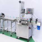
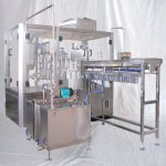
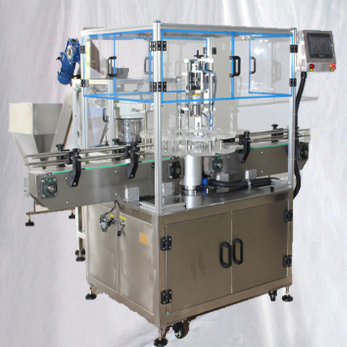
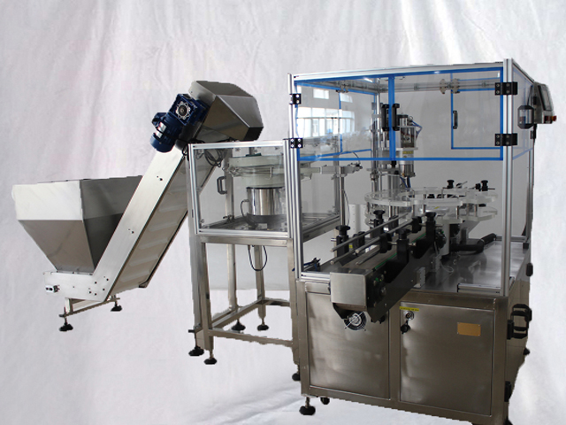
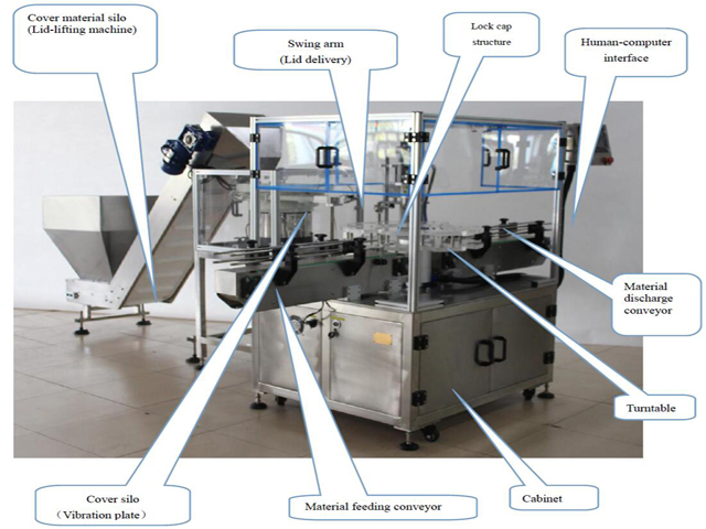
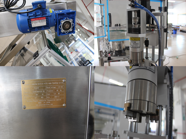
Capping Machine In Details:
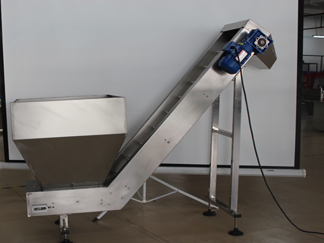
Structures Of The Machine
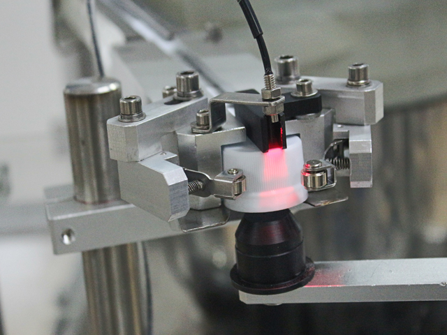
Optical Fiber Electric Eye Description
Electric Eye To Detect Bottles:
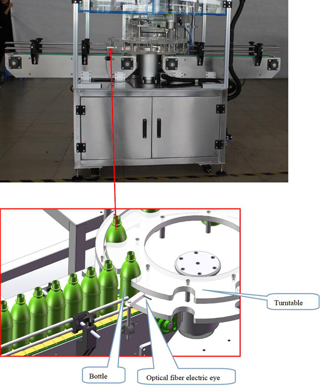
When it is operated in automatic mode, the purpose of this electric eye is to detect incoming bottles.
When the incoming bottle is detected, the "turntable" rotates.
Lid-Delivery Electric Eye
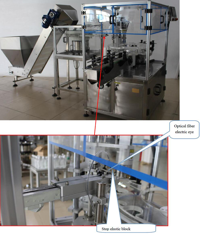
When it is operated in automatic mode, the purpose of this electric eye is to detect incoming covers.
When the incoming lid is detected, the "taking-out mechanism" rises for taking material.
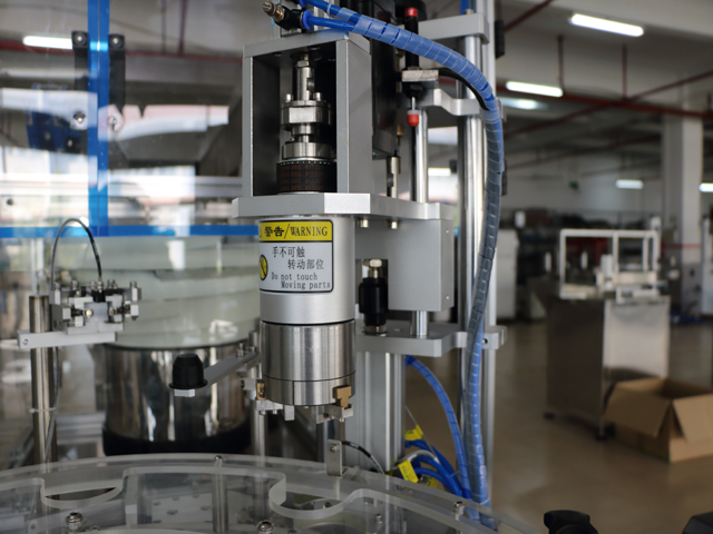
Lid-Delivery Electric Eye
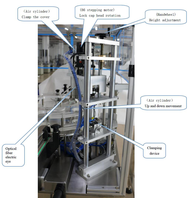
When it is operated in automatic mode: The purpose of this electric eye is to detect incoming bottles.
When the incoming bottle is detected, the "lock cap mechanism" rotates the lock cap downwards.
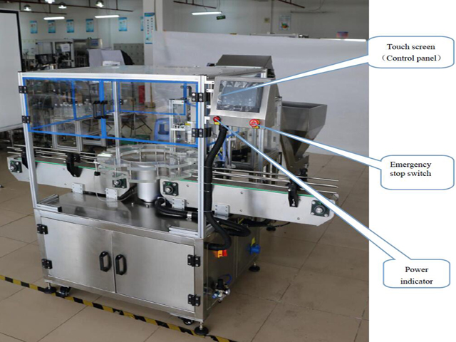
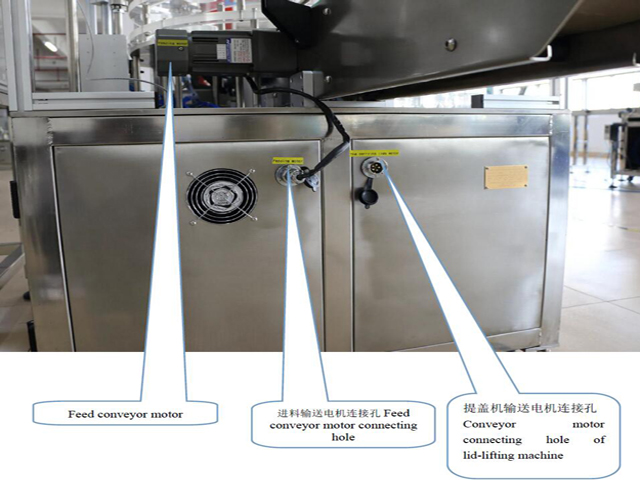
Switch Button And Wiring Port
Touch Screen And Emergency Stop
Feed motor and lid vibration plate controller
Vibration plate controller
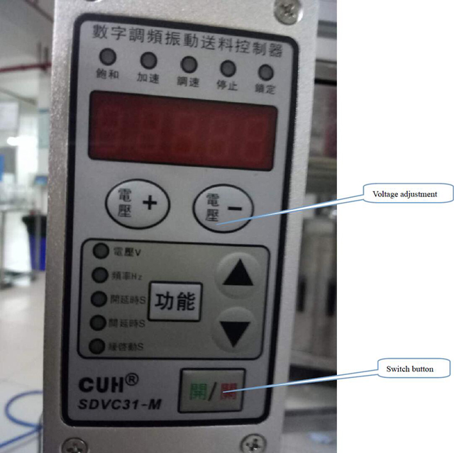
Vibration plate controller: By adjusting the voltage, adjust the discharging speed.
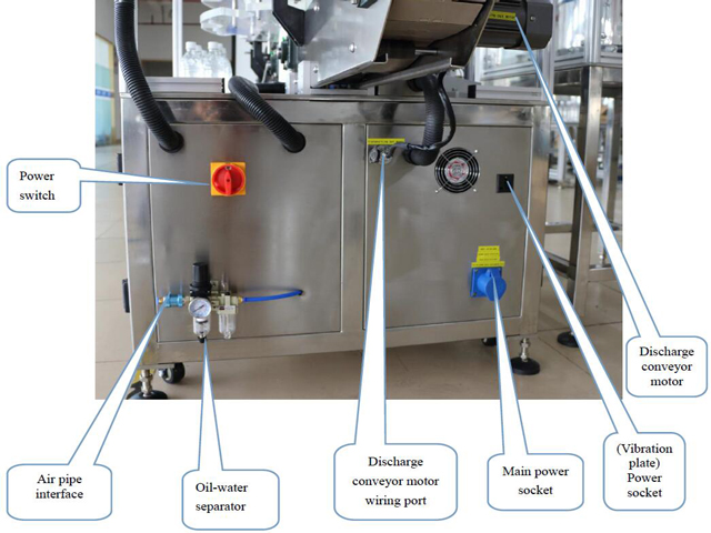
Power switch and sockets
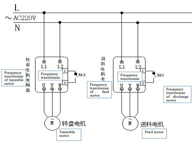
Motor controller
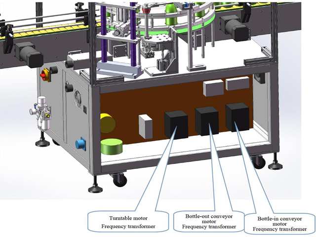
Frequency transformer: By adjusting the frequency transformer button, adjust the motor speed.
Alarm And Trouble-Shooting Method:
1. Emergency stop has been pressed. Push the emergency stops on the machine cap and next to the touch screen.
2. The output reaches the set value. Set the output, press the clear button to clear the current output.
3. When caps are not detected for a long period of time, please check. Check the bottle cap induction fiber as to whether it is well provided. Check whether caps are in place or not.
4. When bottles are not detected for a long period of time, please check. Check as to whether bottles are in place.
Electric Eye Adjusting:
Amplifier Structure
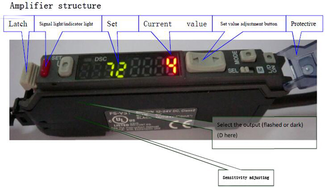
Diagram For Optical Fiber:
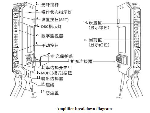
1. Optical fiber lock bar
2. Operating status indicator
3. Set
4. DSC indicator light
5. Digital monitor
6. Manual button
7. Extended protection cover
8. Expansion connector
9. Power Selector Switch
10. Mode button
11. Output selector
12. Cables
13. Dust protector
14. Set value (In green)
15. Current value (In red)
Working Process For The Fiber Optical Setting
- When the electric eye falls in the gap, the red current value is 144.
- When the electric eye falls on the label, the red current value is 4.
- Adjust the set value",about 1/2 of the value that the electric eye is on the body paper (in the gap between the objects to be detected) and the value that the electric eye is on the paper the set value is (144 4)/2=74, adjust the manual button to adjust the set value to be 74.
- Move the label gap back and forth in the electric eye location and the red “signal light/indicator light”.
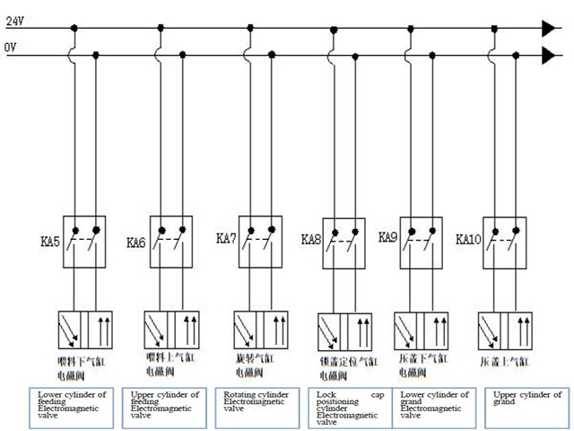
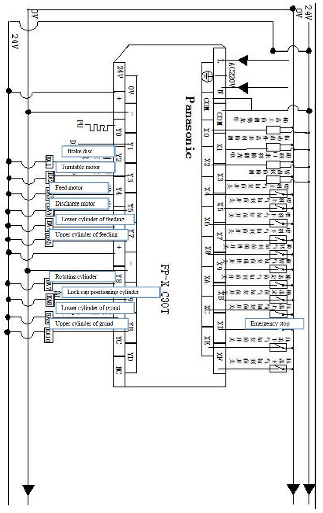
Circuit Diagram
Maintenance Bottles Capping Machine
1. It is necessary to check and maintain the machine to elongate the machine and optimize the function of machine;
- The working machine should be maintained every three month;
- The bearing and gear transmission part must be lubricated with the grease;
- The lubrication must be done periodically;
- The slide way oil (N68) should be added into the part like reciprocating mechanism motion or lifting two times every day;
- The automobile oil(N68) should be added into the rotary or swinging parts;
- Every half month add the grease into the cam slot;
- Every month one time for oil nozzle by adding the grease;
2. Never use metal tools to hit or scrape the surface where the bonding is conglomerated on the parts like components or mold.
3. If the machine stops running for a long time add the grease for lubrication in the parts like transmission or bearing part; Also treat the machine with water-proof protection。
4. Never put any objects on the machine lest it damage the machine.
5. Clean the dust inside the components periodically also check all the screws and fix any screw loosened.
6. Check the screws in the terminals for wiring at a certain time and be sure the screw is fixed;
7. Check if there be any loose station in the stretched wiring path from the electric boxes; If the part is too loose re-fix the screw in order to avoid the abrasion or damage in the insulation layer which may cause the electric leakage.
8. Check the easily-worn pats and change the damaged one on time;
You May Like
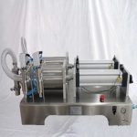
 Two Heads Pneumatic Gear Oil 5000ml Filling Machine Semi Automatic
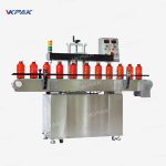
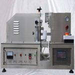
- Automatic Aluminum Induction Sealing Machine With Screw Capping Machine
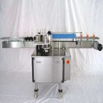
- Linear Round Glass Plastic Bottles Cold Paste Wet Glue Labeling Machine
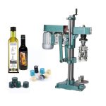
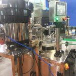
- Semi Automatic Glass Bottles Aluminum Metal Caps Ropp Capping Machine
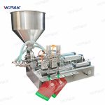
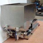
- Semi Automatic Pneumatic Stand Up Bag Juice Cream Filling Machine
- Ultrasonic Plastic Laminated Collapsible Squeeze Tube Sealing Machine
- Customized Monoblock Small Bottle E Liquid Liquid Filling Capping Line
- Semi Automatic Pneumatic Cream Jam Pepper Sauce Filling Machine
- Automatic Inline Screw Capping Machine For Plastic Bottles
- Automatic Spout Stand Up Bags Soybean Milk Juice Filling Capping Machine