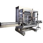
- Model: VK-SVC Vacuum capping machine
- Power supply: AC220V/50-60Hz
- Capping speed: 1200-1500bph
- Power: ≤1.3KW (include vacuum pump)
- Cap diameter: Φ30-Φ85mm, Φ85-Φ110mm
- Bottle height: 50-180mm, 120-250mm
- Bottle diameter: Φ30-Φ80mm, Φ80-Φ150mm
- Limiting vacuum degree: -0.08Mpa
- Capping torsion: 5-25N.M
- Air consumption: 0.5m3/0.7Mpa
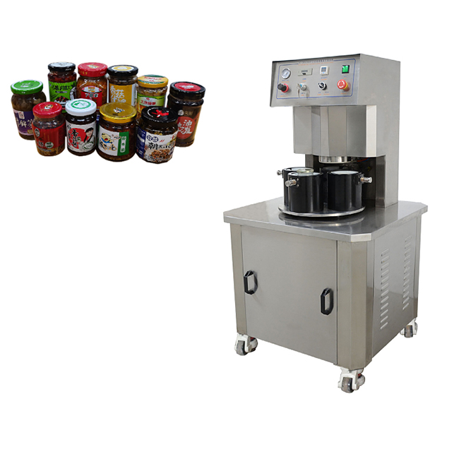
This series capping machine is researched and produced by ourself with years of production experience; is the domestic original creation, it uses a vacuum pump to vacuum, available high vacuum degree, capping torque and vacuum level can be set on demand compatible with a variety of different shapes and sizes of bottles for capping, strong compatibility and easy to adjust.
The main pneumatic and electrical components are from world famous brands, stable and reliable performance.
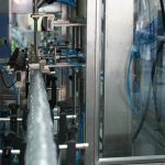
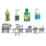
Widely used in glass bottles with tinplate caps vacuum capping for the food, canned food, beverages, condiments, health care products and other industries.
Technical Parameter
- Model: VK-SVC Vacuum capping machine
- Power supply: AC220V/50-60Hz
- Capping speed: 1200-1500bph
- Power: ≤1.3KW (include vacuum pump)
- Cap diameter: Φ30-Φ85mm, Φ85-Φ110mm
- Bottle height: 50-180mm, 120-250mm
- Bottle diameter: Φ30-Φ80mm, Φ80-Φ150mm
- Limiting vacuum degree: -0.08Mpa
- Capping torsion: 5-25N.M
- Air consumption: 0.5m3/0.7Mpa
Operation Instruction For Semi Automatic Vacuum Capping Machine
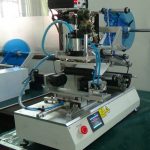
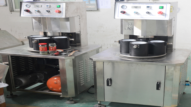
Structure And Working Priciples
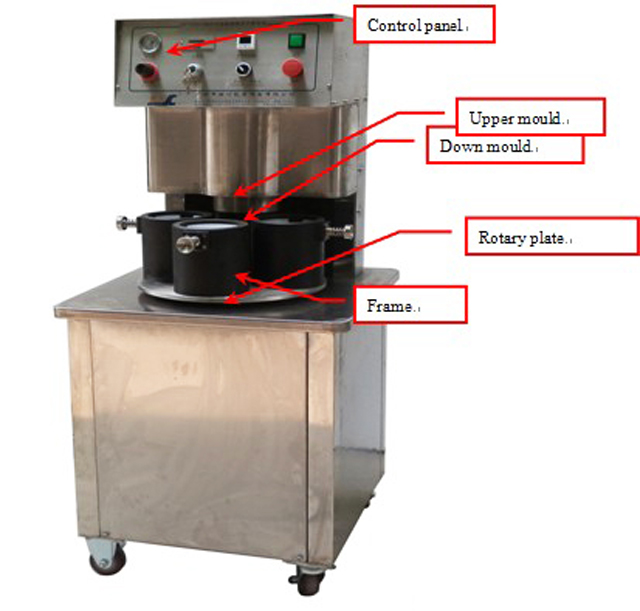
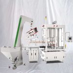
Picture 1: Vacuum capping machine
Working Principles And Functions

This machine is consisted of machine frame, upper mould down mould, rotary position system, capping structure, vacuum system, electric and pressure control system.
Working as: put the glass with caps into the down mould, then put the down mould down to the center of the capping head by hand. Then the machine will be automatically capping with vacuum.
This Machine Has Below Functions As:
When you put the down mould to the center of the capping head, the machine will automatically capping with vacuum;
The lowest vacuum set function: if the machine can not reach the vacuum degree as set before, the machine will not working for the next procedure;
Capping torque function: The capping head is moved by air cylinder, and can be adjusted by pressure;
Main Structure And Components:
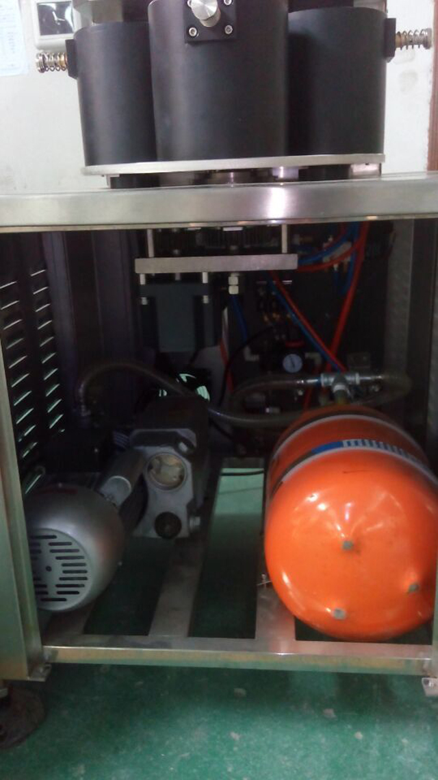
Vacuum pump and vacuum tank:
Vacuum pump and vacuum tank is used to achieve vacuum function, the vaccum pump should be with vacuum oil, half of vacuum oil inside is ok. Not allowed to use the machine if there is no more vacuum oil inside

Picture 2 Vaccum tank and vacuum pump
Pls connect the vacuum pump and vacuum tank as above picture and supply power
Rotary plate structure

Picture 3
This rotary plate is moved by 4 steps
To ensure rotary plate moved steadily, this rotary plate adopt 3 friction plates to supply resistance to ensure steady movement. Must keep the machine clean while working, and the friction plates will be wear gradually, check regularly and change regularly.

Picture 4
The rotary plate is moved by main motor, when the signal detector move to the start proximity switches and get signals(signal detector and proximity switches is about 2-3mm), upper mould move to capping, when it is capping, the motor still working, when the signal detector move to safety proximity switches and get signal, the motor stop working.

Picture 5
Arm copper sets will be wear while working, must put some grease onto it regularly and change when it is damaged. When change you can see picture 5
Capping structure
Capping head

The capping head is moved by cylinder to lift and down, when the capping head is down to capping and reach the vacuum degree as set before, the capping head will move to the next procedure. The capping torque can be adjusted by capping pressure button on the control panel (As you can see in the control panel)
The red rubber inside the capping head is the easy wear part, need to check and change often. When capping, the capping head must put tight to the caps, you can put something inside the down mould to achieve different heights. But the height can not be too much, or if it is too height, you can not achieve vacuum function, but if it is not enough height, it can not be capped. Usually the distance for the caps and top of the down mould is 16mm-19mm
Bottle click device

Picture 7
Bottle click device is to fix the bottle while capping, when the rotary plate is to position, the bottle click cylinder move to fix the bottle to ensure good capping.
Installation
1. The machine must be in a clean and safe place
2. Be sure the emergency stop is available(picture 5)
3. Supply with power to check
4. Connect the machine with gas pipeline to the oil and water separator, adjust air pressure to 0.6Mpa
5. Connect the vacuum tank to the machine. Make sure no gas leak.

Picture 8
Control panel operation

Pictures
The control panel consist of capping pressure table, capping pressure adjustment, counter, power switch, vacuum adjustment and emergency stop.
- The capping pressure adjustment can be used to adjust the capping torque, when it is clockwise, the pressure increased, the capping torque is stronger, when it is counterclockwise, the pressure decreased, the capping torque is smaller.
- Emergency stop, when something emergency happen, push the emergency stop switch, then the machine will be in safe situation
- The counter is to count how many glasses you have produced, if you put the reset button, the counter will be count as zero.
- If need to adjust the vacuum degree, push the “M” in the vacuum adjusted table, and it will display”St1”, push “︽”“︾” to adjust
Oil and water separator and pressure and adjustment ( Picture 10)

Picture 10
Oil and water separator is consist of hand control valve, pressure adjust, air pressure table, oil adjust, air filter and lubricator;
Hand control valve is to turn on and off the whole air supply of the machine;
Pressure adjust is to supply the pressure to the machine, when it is clockwise, pressure increased, when it is counterclockwise, pressure decreased;
Air pressure table is to display the machine working pressure;
Oil adjust is to supply oil to the machine, when it is clockwise, the oil decreased, when it is counterclockwise, the oil increased;
Air filter is to remove the water of the compress air, when the pressure of the oil and water separator is zero, the air filter will be remove the water automatically;
Lubricator is to supply oil for the machine, first need to shut off the air supply, and put some oil into the lubricator, about 2-3 months per time.

Electric drawing for vacuum capping machine
You May Like
 High Speed Rotary 8 Heads Capping Equipment For Pump Caps
- Automatic Linear 10 Heads Gravity Filling Machine
- Automatic Bottle Filling Capping Labeling Cartoning Overwrapping Machine
- Automatic Empty Soft Squeeze Toothpaste Cosmetic Tubes Labeling Machine
- Automated Olive Oil Filling Ropp Capping Labeling Machine
- Tunnel Type Water-Cooled Aluminum Foil Induction Sealing Machine
- Pneumatic Flat Square Round Bottles Rolling Labeling Machine With Coder
- Automatic Pesticide Liquid Fertilizer Filling Capping Labeling Line
- Automatic Easy Open Aluminum Pop Containers Can Sealing Machine
- Automatic Bottle Caps Heat Shrinking Sleeve Labeling Machine